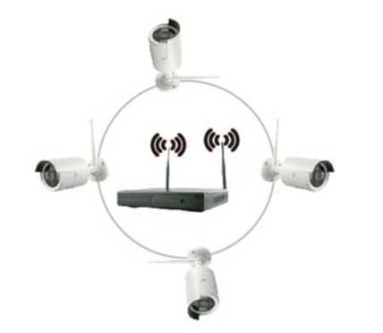
Wireless NVR Kit Setup Guide, Recommend NVR put in the center of the monitored area. try to avoid obstacles between IPC (wireless camera) and NVR. When connected to 4 IPC. There is no obstacles between the NVR and the IPC. IPC placed in the spherical coverage to NVR center of the sphere with a radius of 60 meters. when one wall between them .the radius decreases to 30 meters.
1.Product Function Introduction
- H.264 compression. 4 Channels Full real time D1. 720P wireless NVR.
- Internal high performance and high stability Wi-FI router module. Support 802.11b/g/n protocol. 150Mbps.
- Auto code through Ethernet cable to connect wireless camera.
- Video Preview / Record / Playback / Backup.
- Easy to operate.(Wifi simple match and clear configuration wizard)
- Support ONVIF. N1 protocol.
- Support P2P.DHCP.DDNS.PPPoE.E-Mail.FTP network service function.
- Support video loss. motion detection and alarm output (Sound/Email Push/FTP).
- Support Android /Apple system. Support local view and remote view.
- Support PC client. Support local view and remote view.
- Support user management.
After receive our parcel. Please check whether the parcel is normal or damaged. Check the device’s accessories are complete or not. The following is the general list:
| Package List | |
| 1 x 4CH NVR | 2 x Antenna for NVR |
| 4 x 720P camere with antenna | 5 x Power supply(12V-2A) |
| 1 x Network cable(1 meter} | 1 x Mouse |
| 1 x User manual | 1 x Screw bag |
- In order to extend the life of the machine. the machine should be away from water. heat. dust environment. and in a well ventilated place.
- Please use SATA hard drive which purchased from normal channel.
- Prior to use. make sure the NVR is properly grounded. can not exceed the power supply voltage in the range.
In order to use the RECORD and PLAYBACK features. please install a hard drive(HDD) inside the DVR/NVR unit. It supports SATA interface.
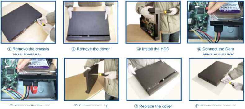
(D Connect the Power cable to the HDD.
® Replace the screws securing the cover to the chassis
©Fix the screw of thee hard disk
Note:
When you plug in the data cable and power cable. Please note only one side of the cable can be plug in.If you can’t plug in.Try another side to plug in.
cover’s screws.
cable to the HDD
Want to know what storage of HDD you need?
One camera works 24 hours/ one day. need 20GB HDD storage.
1T HDD support 4 cameras work for 24 hours /one day for 15 days.
Recommend NVR put in the center of the monitored area. try to avoid obstacles between IPC (wireless camera) and NVR. When connected to 4 IPC. There is no obstacles between the NVR and the IPC. IPC placed in the spherical coverage to NVR center of the sphere with a radius of 60 meters. when one wall between them .the radius decreases to 30 meters.
Wireless NVR Kit Setup Guide
Read More :
When there are two walls between them. The radius decreases to15 meters (Due to coverage obstacle physical nature and the surrounding environment by. this data is only for reference)
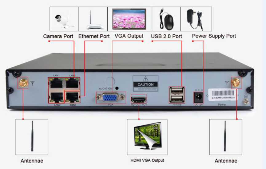
Wireless kit connection diagram Picture 1
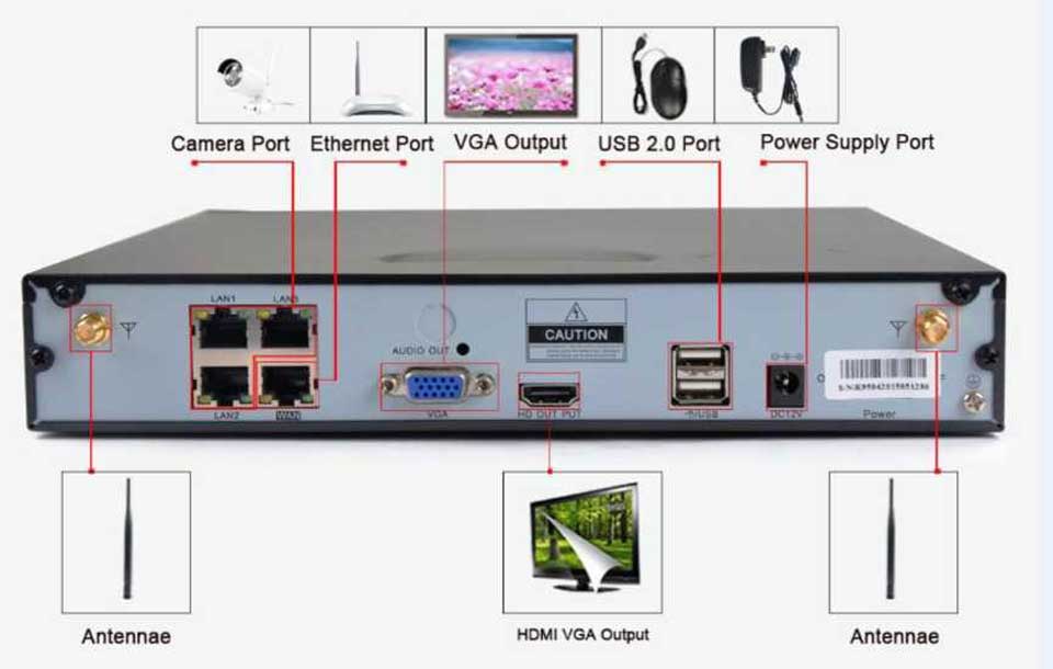
Note: Please note there is only one WAN port. Which is Ethernet port The other three LAN ports is used to connect IPC when operate “Code match”.
After connect all the devices. when images shows on the monitor. Thatmeans the kit is working properly. They can be mounted to a predetermined position.
4.Put the IPC in the preset position
-
- nstall the cameras in effective coverage area of the wireless signal .and provide a 12V supply;
- Power for about 1 minute. The image will appear on the monitor.
- If no image. indicating that the distance between camera and NVR is too far away. we need to shorten the distance.
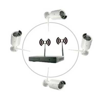
Correct
Incorrect
Make sure NVR and IPC ‘s antenna are at the same height and parallel to each other. if not at the same height. IPC antenna should be spherical tangent. NVR is the centre of sphere. The IPC’s antenna can’t be directly towards the NVR. As above picture
When you login. The interface is shown as below. The default user is admin. The default password is blank. No need to input anything in it.
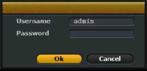
Login interface Picture 2
After a successful login. the system will automatically open the “Setup Wizard” interface to guide the user to setup the basic settings.
- General Settings. User can setup urban. time. language. key type. The interface is shown as below. Then click<Next>to the next step.
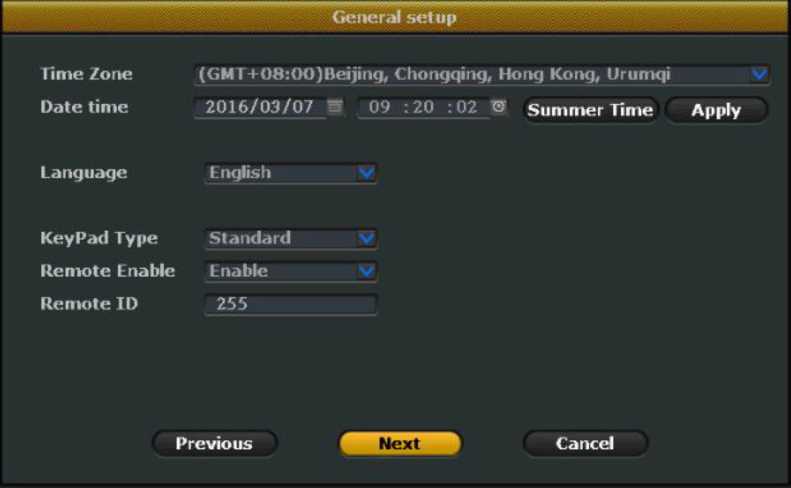
General setup Picture 3
- .HDD Setup. It displays the current list of drives. including type. capacity.
used. status. formatting state. To format the hard disk. User can first select the appropriate hard drive. and then click Format button. wait a
moment. The format will be done. The interface is shown as below.
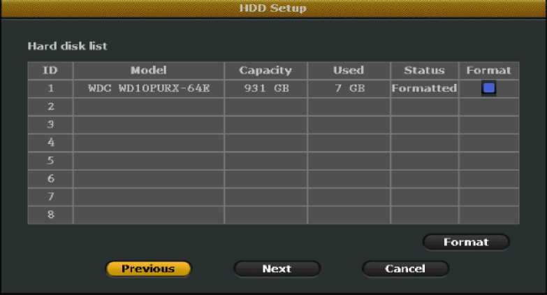
HDD setup Picture 4
- .Record Setup. User can select Schedule Record or Motion Detection
Record.
Schedule Record: Select the channel. weekday. Click ”Time”. Input begin time and end time in Schedule. User can setup 4 period time. If you want to setup 24 hours recording a day. Input 00:00-23:59.
Motion Detection Record: Select the channel. weekday. Click ”Motion”.
Note: Please use the same method to setup other channels’ record plan . If the record plan is the same with the first one. Click “Copy to” . Select other channels to copy it.
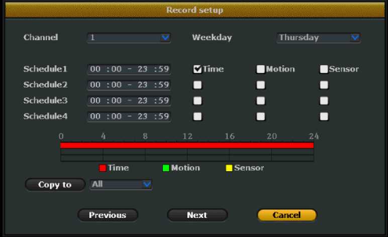
Record setup Picture 5
- .Network Setup.
- For remote view. User need setup IP. Gateway. Please make sure theIP address. Gateway are in the same network segment with your router.
For example: If the router’s IP Address is 192.168.1.1. Then the NVR’s IP
Address and Gateway should be in the 192.168.1.x range.
- After modify the IP and gateway. If the device still offline. User also
need to modify Preferred DNS to 8.8.8.8 or 8.8.4.4 .
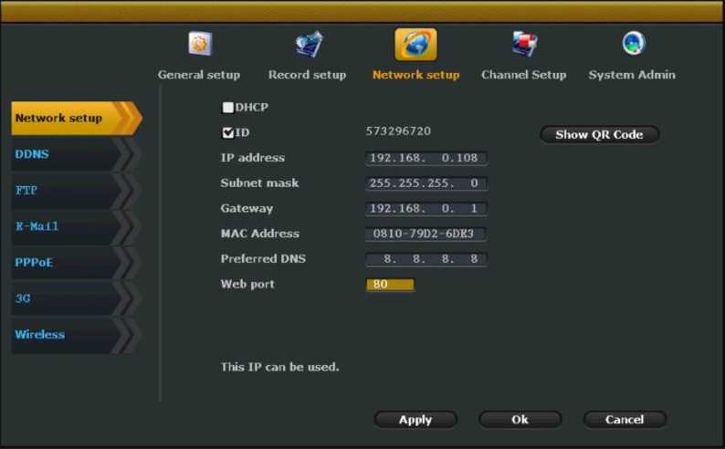
Network setup Picture 6
Note: User also can select <DHCP> to obtain the IP address automatically. If user need to modify IP address and gateway. Please do not select <DHCP>.
Function Introduction: To search all the IPC devices which are in the same network segment with the NVR.
Steps: Right click on the NVR. Click<IPC Add>.The Interface is show as
below. Click<Refresh>to search for the IPC devices.
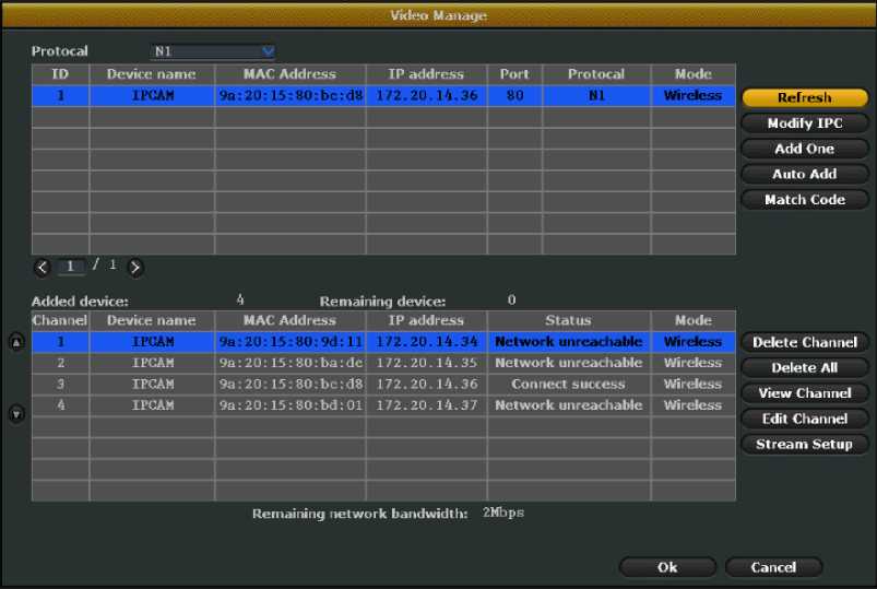
Search IPC Picture 7
Function Introduction: To add the IPC devices
For the original wireless kit. The IPC devices will be added automatically. After you connected all the devices. All the images will be shown on the monitor. If exchange anther new camera or NVR. Please use the “Match Code” to add the IPC device.
Steps: First use the Ethernet cable in the package to connect the IPC and NVR’s LAN port. Right click on the NVR. click<IPC Add>.The interface is show below. Click<Match Code>-<Yes>.Then please wait patiently for the results of the code. After successfully match code. Unplug the Ethernet cable. if the code fails prompted. please click” refresh “.If no image shown on the monitor. please check the connection of Ethernet cable.
then re-connect to operate “match code”.
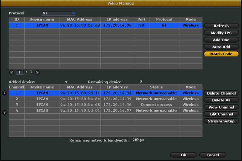
Match code Picture 8
Add One (for wired connection)
Steps :To use “Add one”. User need to connect a Ethernet cable to the camera and the NVR’s LAN port for wired transmission. The maximum transmission distance it support is 100M. Right click on the NVR.
Click<Add IPC>-<Add One>.The system will automatically add the IPC. Images will be shown on monitor. Please do not unplug the Ethernet cable.
Function Introduction: Delete the IPC device
Steps: Right click on the NVR. Select <Add IPC>.Then will pop up a page.
Select the IPC device .Click<Delete Channel>.That is OK.
Function Introduction: Edit IPC device’s protocol. IP address. Port.
Stream type and image Rollover.
Steps: Right click on the NVR. Click<IPC Add>.Then will pop up a page.
Select the IPC device. Click<Edit Channel> to edit above parameters.
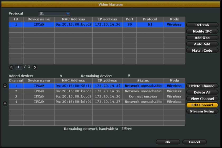
Edit channel Picture 9
Note: Please do not modify <User> and <Password>. To manage user.
Follow 4.11.2 chapter.
Function Introduction: Edit IPC device’s stream. Resolution. Frame rate.
1 frame interval.H.264 profile
Steps: Right click on the NVR. Click<IPC Add>.Then will pop up a page.
Select the IPC device. Click<Stream Setup> to edit above parameters.
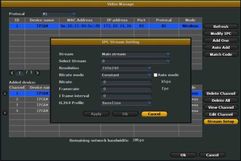
Stream setup Picture 10
Note: There are main stream and sub stream options. In better network conditions. choose the main stream to obtain better quality pictures. Under poor network conditions. select the sub stream to ensure fluency monitoring.
Introduction: For remote monitoring. you need to set up the network.
Steps: Follow “4.1 Setup Wizard-Network setup” Page
Web port: The web access. PC client. Mobile client all use the same web port. The default web port is 80.
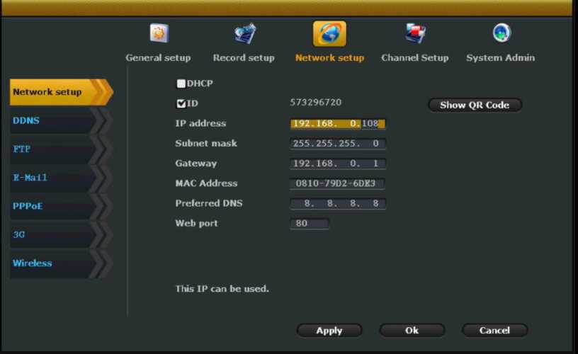
Network setup Picture 11
Introduction: send email to user to notify Alarm and video test
results. Support Hotmail and Gmail email box.
- .Right click on the NVR. Click <System setup>-<Network>-<Email>.The interface shown as below:
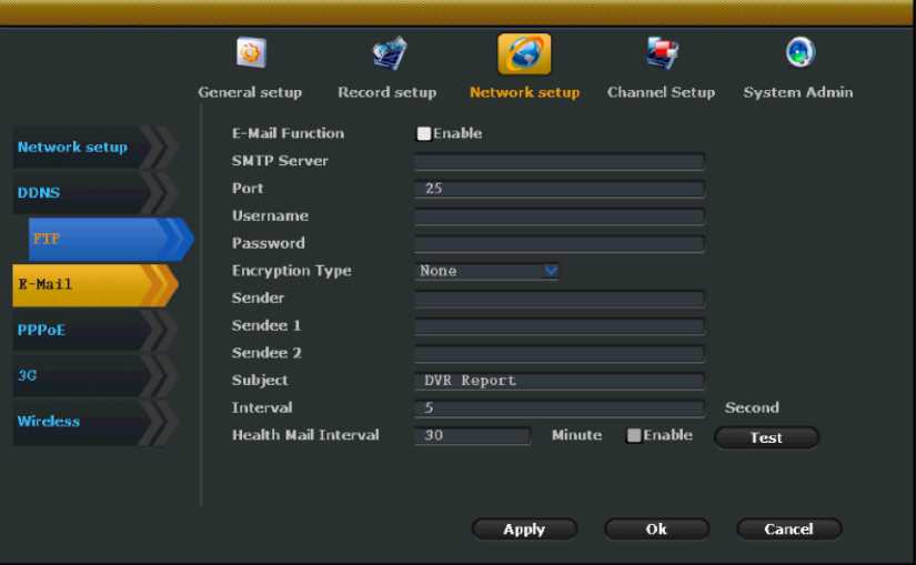
Email push setup Picture 12
- .Enable Email function. Input the parameters as below:
| Function name | Hotmail email box setup | Gmail email box setup |
| SMTP server | smtp.live.com | smtp.gmail.com |
| Port | 25 | 25 |
| User name | Your email address | Your email address |
| Password | Your email box password | Your email box password |
| Encryption Type | Keep the default settings. if fail to test. modify it to SSL | Keep the default settings .if fail to test. modify it to SSL |
| Sender | your email address | your email address |
| Sendee1 | Your email box which used to receive alarm emails. Also can be the same with Sender. | Your email box which used to receive alarm emails. Also can be the same with Sender |
| Subject | Edited by user | Edited by user |
| Interval | Time interval to receive email | Time interval to receive email |
| Healthy mail interval | When DVR in normal operation. How often will it send a Email | When DVR in normal operation. How often will it send a Email |
| to the Sendee’s email box. | to the Sendee’s email box. |
- .After input the above parameters. Click<Test>. Click<Apply>-<Ok>.If failed to test. Please modify the Encryption Type to SSL. Then check all the other parameters to make sure they are correct.
- .Click <System setup>-<Record Setup>.Click <Sensor Setup> on the right.
Select the channel. Tick <Email Notice>.As follows. To set email push to other channels. Click<Copy to>.Then select the channel.
Click<Apply>–<OK>.
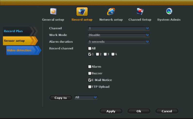
Email push setup Picture 13
5. Click<System Setup>-<Record setup>.Click<Video detection> on the right side. Select the channel. Select <Motion> in Detection options.
Tick<Email notice> Saved. As follows. To set email push to other
channels. Click<Copy to>.Then select the channel. Click<Apply>–<OK>.
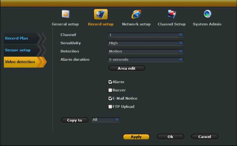
Email push setup Picture 14
Note: If the E-Mail function does not work. make sure the mailbox is
turned SMTP service
Generally. Users do not need to modify wifi configuration. Please operatethese steps under the guidance of our professional staff.
Steps: Click<System Setup>-<Network Setup>-<Wireless>. The
interface is shown as below.
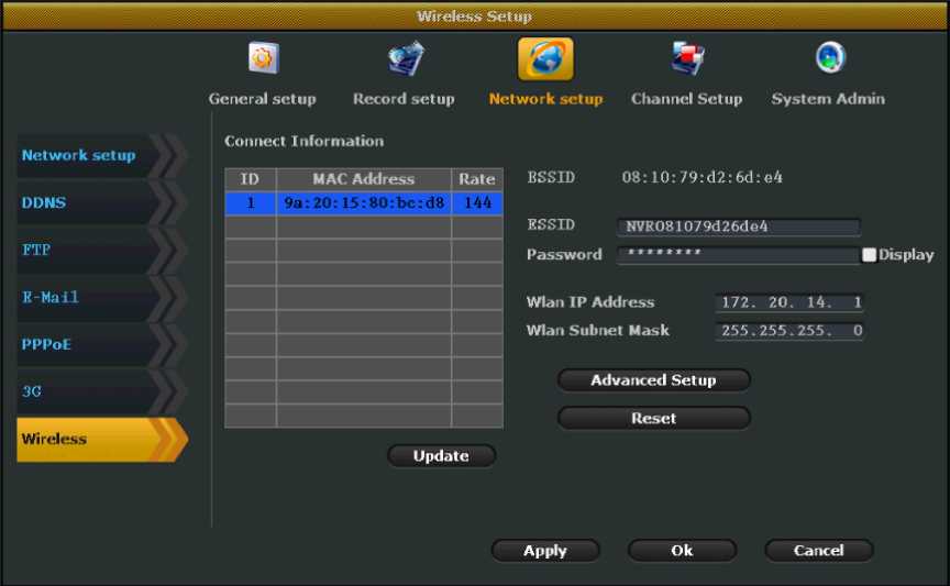
Wifi configuration Picture 15
Note: Click <Reset>the wireless module information will be reset to the factory settings.
Function Introduction: use manual recording function. the user can quickly turn on or off the video.
Steps: Right click on the NVR. Click<Manual record>.The interface is shown as below. Select the channel for manual record. User also can click<All on> or <All off> to turn on or off the video. Then click Ok.

Manual record Picture 16
Note: Recording priority: alarm recording > motion recording > Manual recording > Schedule recording
Function introduction: Set the schedule recording function. User can set a period time for recording.
Steps: Click<System setup>-<Record setup>- <Record plan>.The interface is shown as below:
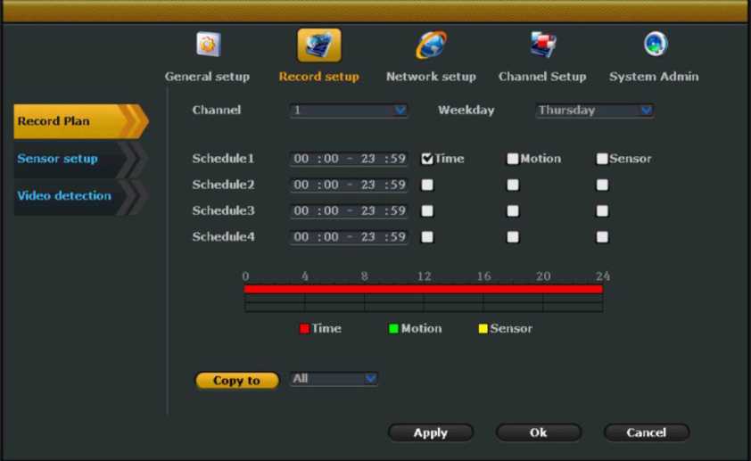
Schedule record setup Picture 17
Select the channel. weekday. Click ”Time”. Input begin time and end time in Schedule. User can setup 4 period time. If you want to setup 24 hours recording a day. Input 00:00-23:59. Please use the same method to setup other channels’ record plan . If the record plan is the same with the first one. Click “Copy to” . Select other channels to copy it.
Function Introduction: Setting motion detection recording. the system will record when an object detected motion.
- Click<System setup>-<Record setup>- <Record plan>. Select thechannel. Weekday. Tick <Motion>.The interface is shown as below. To
setup motion record for other channels. Click<Copy to>-<Apply>-<Ok>.
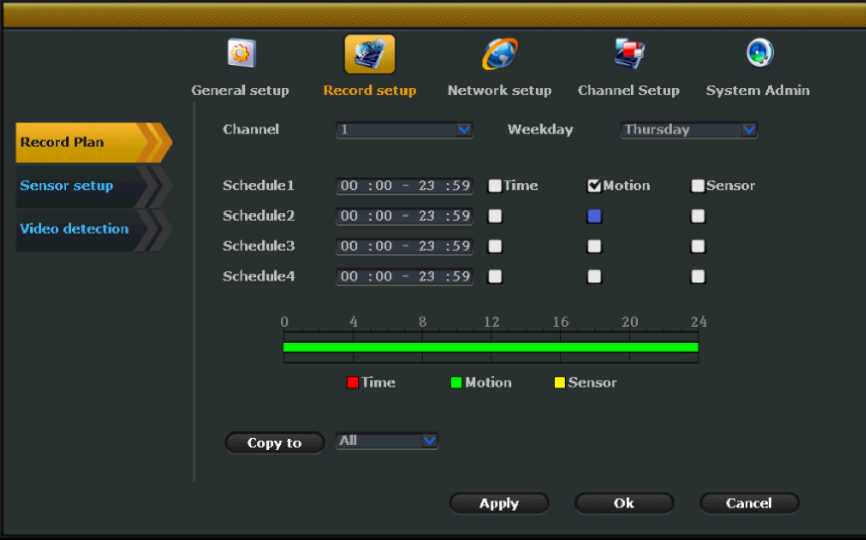
Motion detection record setup Picture 18
2.Click<System setup>-<Record setup>-<Video detection>.Select the channel. Sensitivity. Select <Motion> in Detection option. Select Alarm duration. Motion detection area edit. User can according their requirement to select Alarm. Buzzer. Email notice. FTP upload. To setup other channel for motion detection record. click<Copy to>.Select the channel. Click <Apply>-<Ok>.
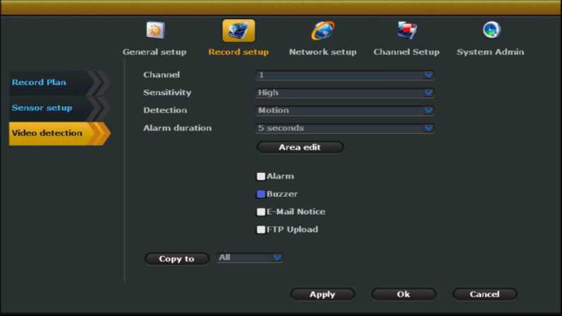
Motion detection record setup Picture 19
Function Introduction : Enable quick playback function. Users can quickly obtain the latest video.
Steps: Right click on the NVR. Click<Video playback>.User can select 5min.10min.30min time to playback the latest video.
Split screen
Video backup
PTZ control
Color adjust
Volume
Manual record
5 Min.
10 Min.
30 Min.
Manual Search
System setup
Setup Wizard
IPC Add
Cxit System
Video playback Picture 20
Note: Before video playback. Please make sure the NVR install a hard disk and the record function is enabled.
Function Introduction : Enables standard playback function. Users can retrieve video data according to time and record type.
Steps: Right click on the NVR. Click<Video playback>-<Manual
Search>.The interface is show as below. Select the channel. Record mode. Input search time. Click <Search>. wait about 30 seconds. Will show the retrieve video. drag the playback bar to the time point you want to play.
Click<Playback>button. The interface of Playback progress bar shown
below :

Video playback Picture 21
Button Introduction
![]()
![]()
![]()
Previous frame
Next frame
Pause
lüü! Play
fast forward
Note: it support 2x / 4x / 8x / 16x-speed playback
Function Introduction: Copy the video files to USB flash disk.
- .Plug a USB flash disk to the USB port of the NVR.
- .Right click on the NVR. Click<Video copy>.The interface is shown as below:
| Channel | Ql □ | 2 Cl 3 D4 Cl All | |||||||
| Record mode | Cl Manual Cl lime | Cl Motion Cl Sensor | |||||||
| Search time | 2016/03/07 15 00 :00 – 2: | Î :59 | Search | ||||||
| ID Channel | 1 Mode | Begin time | tnd time | Duration | Size | Select | |||
| i r | Time | 09:19:10 | 09:24:56 | 00:05:46 | ■ | ||||
| 2 | 3 | Time | 09:00:00 | 09:18:21 | 00:18:21 | 110M | |||
| I | 3 | Time | 08:00:00 | 08:59:59 | 00:59:59 | 4O9M | |||
| * | 3 | Time | 07:00:00 | 07:59:59 | 00:59:59 | 112M | |||
| 5 | 3 | Time | 06:00:00 | 06:59:59 | 00:59:59 | 106M | ■ | ||
| * | 3 | Time | 05:00:00 | 05:59:59 | 00:59:59 | 106M | ■ | ||
| 7 | 3 | Time | 04:00:00 | 04:59:59 | 00:59:59 | 106M | ■ | ||
| 9 | 3 | lime | 03:00:00 | □3:59:59 | 00:59:59 | 106M | ■ | ||
| < 1 | /2 | > | USB storage | c | Cancel | ||||
Video backup Picture 22
3.Select the channel. record mode. Input search time. Click<Search>.Wait for 30 seconds. The searched videos will show on the list. Select the video for backup. Click<Video copy>.That is Ok.
Function Introduction : When detected moving objects. this unit triggers an alarm and outputs an alarm.
- .Right click on the NVR. Click<System setup>-<Record setup>-<Video detection>.The interface is show as below.
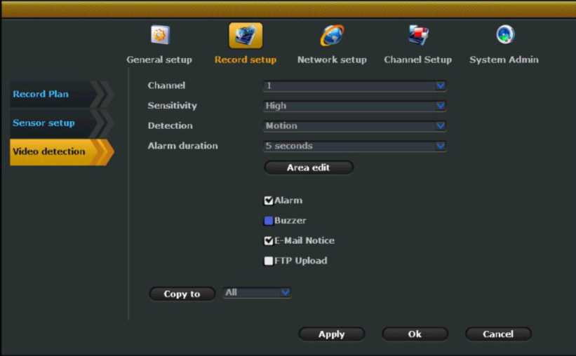
Motion detection Picture 23
2.Select the channel. Sensitivity. Select <Motion> in Detection option. Select Alarm duration. Motion detection area edit. User can according their requirement to select Alarm. Buzzer. Email notice. FTP upload. To setup other channel for motion detection. click<Copy to>.Select the channel. Click <Apply>-<Ok>.
Note: If you want to select <Alarm>.You also need to operate this step.
Please click<Record setup>-<Sensor setup>.Select the channel. Modify the <work mode> to enable status.
Function Introduction: Detect if lose a channel video signal. User can deal with it on time.
Steps: The operate steps is almost the same with motion detection alarm ‘s .The only difference is select <Video loss> in Detection option. Not <Motion>.
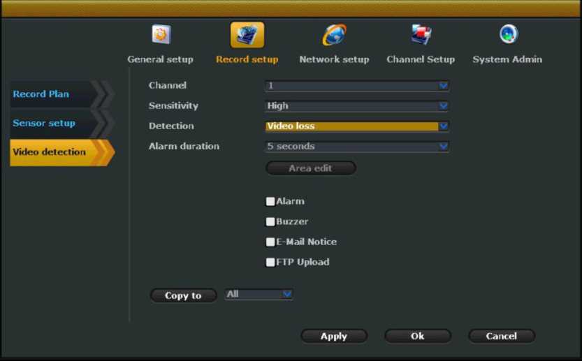
Video loss alarm setup Picture 24
Function Introduction: It is used to format the hard disk.
Steps: Right click on the NVR. Select <System setup>-<General
Setup>-<HDD setup>. The interface is shown as below:
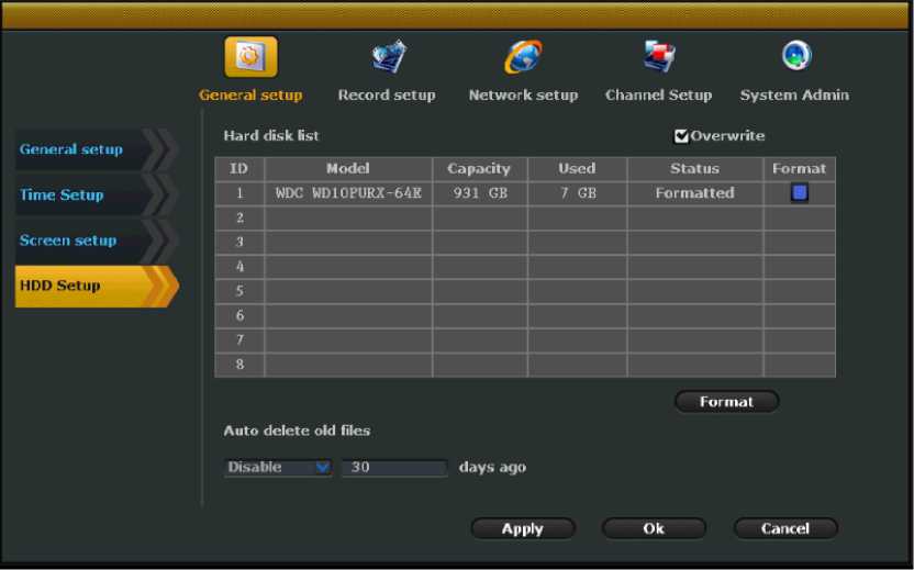
HDD setup Picture 25
- You can see all the information which the unit is connected to the hard disk. including the model. Capacity status. formatting state.
- According to your requirement to select <Overwrite>.Enable this function. When the hard disk is full . it will automatically overwrite the oldest video data.
- To format the hard drive. left-click to select the drive and click
Format” button.
- To automatically delete old files. select “Custom” in the drop-down box and fill in the days.
- Click the “Apply” button to save the settings.
Version info
Function Introduction : User can see device name .Device model. Device
serial number. Hardware version. Software version. Built time.
Steps: Right click on the NVR. Click<System setup>-<System
admin>-<System version>.The interface is shown as below:
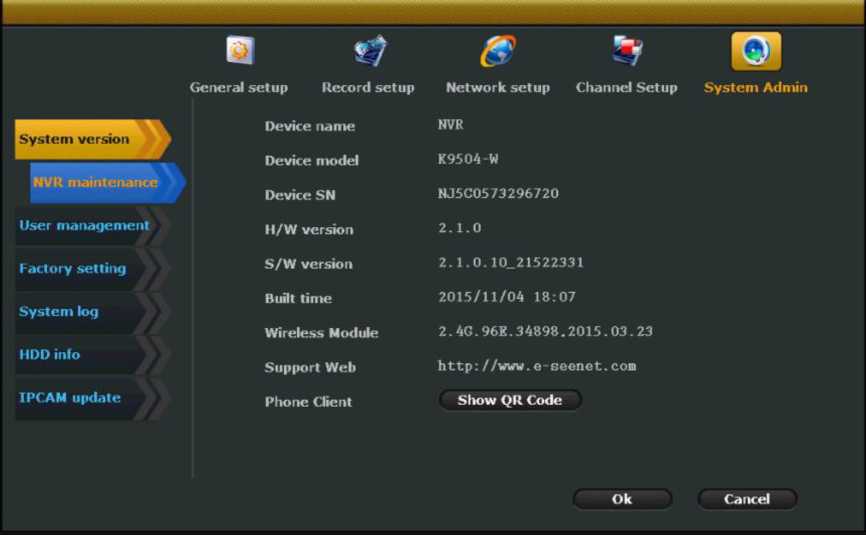
Note: Version information is very important for the maintenance. the user must provide the version information during maintenance.
Function Introduction: Users can view the hard drive information. Such as model. capacity. amount. status. total capacity. the total used and total balance
Steps: Click<System setup>-<System admin>-<HDD info>

HDD info Picture 27
The default user name is admin. The default password is blank. Use do not need to input anything in it.
The admin can add. delete users and edit user’s privileges.
Steps: Right click on the NVR. Click<System setup>-<System
admin>-<User management>.The interface is shown as below:
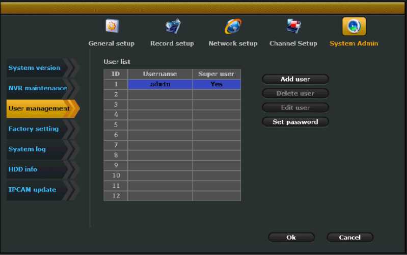
User management Picture 28
Click<Add>.The interface is show as below. Enter the new user name and
password. Setup the user‘s permission. (The super user has all the
permissions. the super user’s default password is blank.)Click OK.
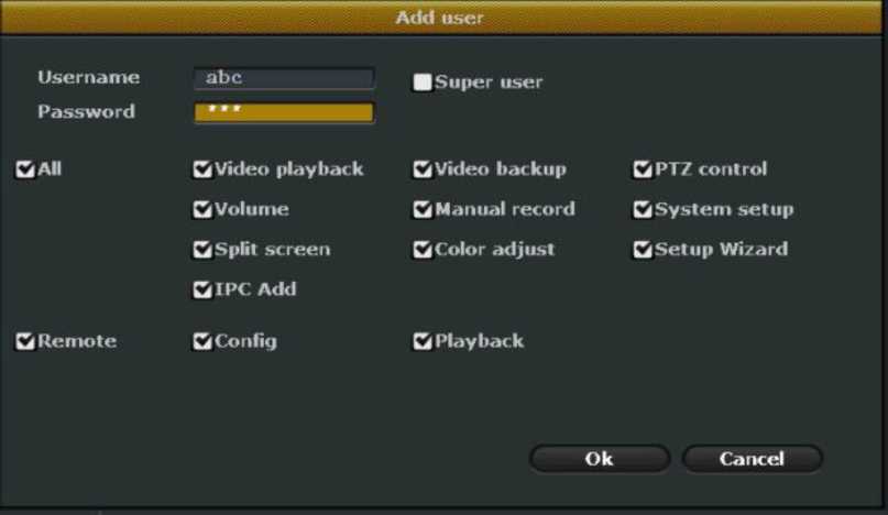
Add user Picture 29
Left click to select the user you want to delete. Click<Delete>-<Ok>.
Note: The super user can’t be deleted.
Click<Edit> to enter edit page. re-edit the user’s permissions. Click Ok.
Saved.
Note: The super user can’t be edited.
Click<Modify password> to modify the user’s password.
Note: The user which is non-super user. only can modify the current
password. It can’t add. delete. edit other users
Steps: Right click on the NVR. Click<System setup>-<System admin>-<Factory setting>.The interface is shown as below. Select the
options you need to restore factory settings .Click<Apply>-<OK>
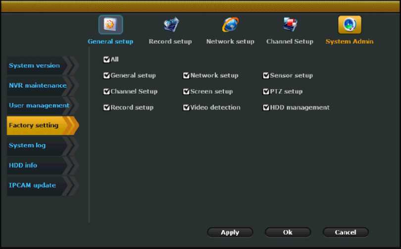
Reset factory Picture 30
Function Introduction: It is used to upgrade system and setup auto maintenance.
Steps:
- .Click <System setup>-<System admin>-<System maintenance>
- .Put the newest firmware under the root directory of USB flash disk.
Plug the USB flash disk into the USB port of the NVR.
- . Click <USB storage > and < system >- Then click <Start>
- . Wait for the upgrade complete. the device will reboot.
- Please make sure put the newest firmware under the root directory of USB flash disk.
- The upgrade include system upgrade. boot screen upgrade and resource upgrade.
- Do not shut off the power when upgrade system. otherwise the NVR can’t reboot.
Steps: Click <System setup>-<System admin>-<System
maintenance>.Enable auto maintenance. Input start time and end time.
Select a weekday. Click<OK>.
Function Introduction: User can according to time type> start time and end time to view the log information. The interface is shown as below:
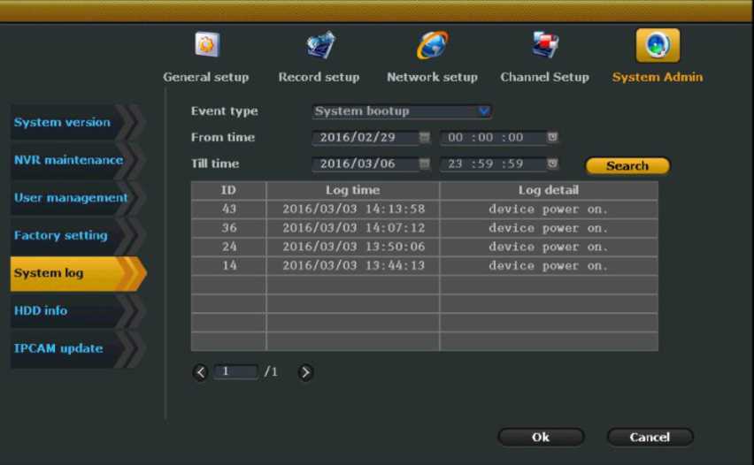
System log Picture 31
Steps: Click<System setup>-<System admin>-<System log>.Select Event type. There are some options. Such as system startup. system shutdown. system configuration changes. Recording. Alarm. warning and all.
Note: log is saved on the hard disk. the log information will be lost if format the hard disk.
1.when the device is in online status. Input the device IP address in the browser bar to enter web access page. For example. If the device IP address is 192.168.0.1.Input http://192.168.0.1 in the browser bar. It support multiple browser such as IE. Chrome. Firefox.
(1)To find the device IP address. Click<System setup>-<Network setup>.
(2)Please make sure the device is in online status before you login.
(3)If the web port was modified.(The default web port is 80).When you input the IP address in browser bar. Please input the web port after the IP address .If you modify the port to 82.Input http://192.168.0.1:82 The port can be set between 80 to 100.
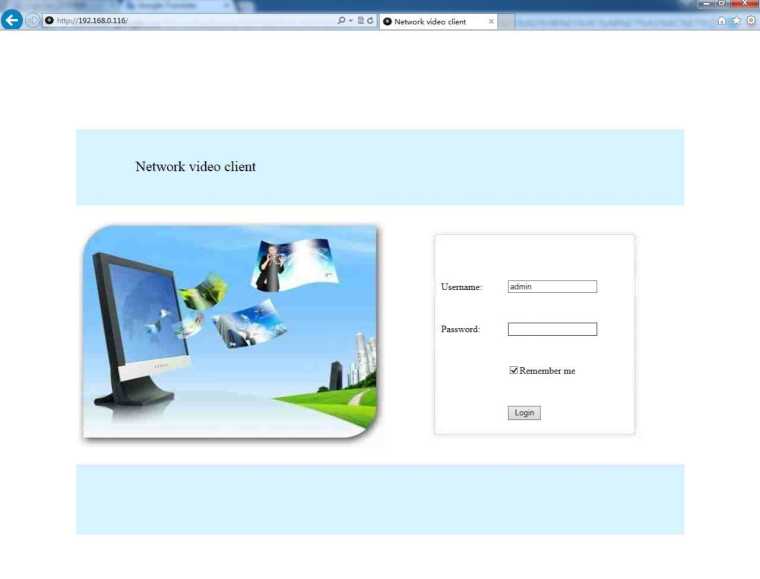
-
- nput user name and password. Click<Login>.will pop up a page as below.

LAN access Picture 33
- .Follow the prompt to download the WebClient.exe active.
- .Then login again. Wait a moment. You can view the picture on your computer.
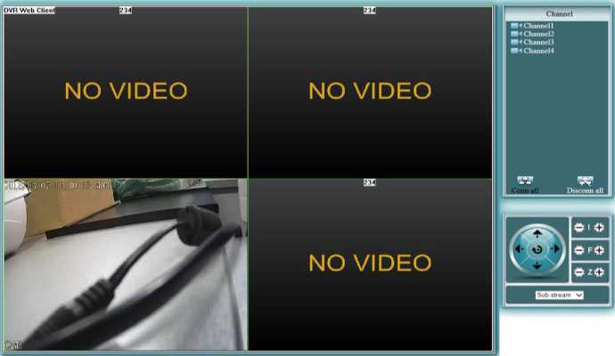
LAN access Picture 34
If the first time the software can not be loaded. the browser needs to do the following settings: Tools -> Internet Options -> Security -> Custom Level -> Enable the Active X controls and plug-ins and finally click “OK”.
After login successfully. The preview interface is shown as below.
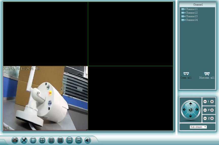
LAN preview Picture 36
Note: If you use non-IE browser. To view the image. Please select Main
stream on the bottom right side. Then you will see the image shown on the monitor.
Click to enter playback page. Select the channel. Type. Input searching time to search. Click the searched video files to playback.
| ?lay By Time | Return |
Channels: 01020304
Types: 0Time 0Motion 0 Sensor 0 Manual
Search date: 12016-3-7 |
Begin time: |0:0:0 | -123:59:59
Total 0 rows Pagesize 10 1/0 Page | Prev 11 Next
LAN playback Picture 37
Note: When a non-super user login. make sure that the user has permission to remotely playback. In System Setup -> System admin -> User Management -> Users to view and edit the permission for remote video playback.
Click Xto enter the configuration page. The interface is as below:
| Devlnfo | Schedule | General | Network | Screen | Video detection | PTZ | Sensor | Return |
| Dev name | NVR. |
| Dev model | K9504-W |
| HW version | 2.1.0 |
| SW version | 2.1.0 10_21522331 |
| Reldatetime | 2015/11/04 18:07 |
| IP | 192.168.0.108 |
| HTTP port | 80 |
| Client port | 8880 |
| UPNP IP | 192.168.0.108 |
| UPNP HTTP port | 60001 |
| UPNP Client port | 60001 |
| Camera count | 4 |
Note: To know about the specific configuration features. see “4.System
Function Introduction”.
When a non-super user login. make sure that the user has permission to remotely configure. Click System setup->System Admin ->User Management – >User to setup the permission to remotely configure.
1.Input www.e-seenet.com in a browser bar to enter the remote access
page. It only supports the IE browser.
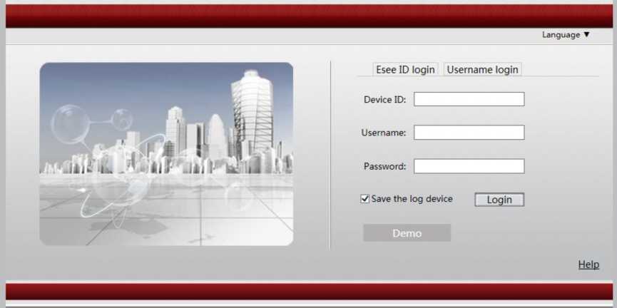
WAN remote access Picture 39
There are two ways to login: 1.Esee ID login 2.Username login
Input Device ID. Device user name and password. Click login. The image
is shown as below:
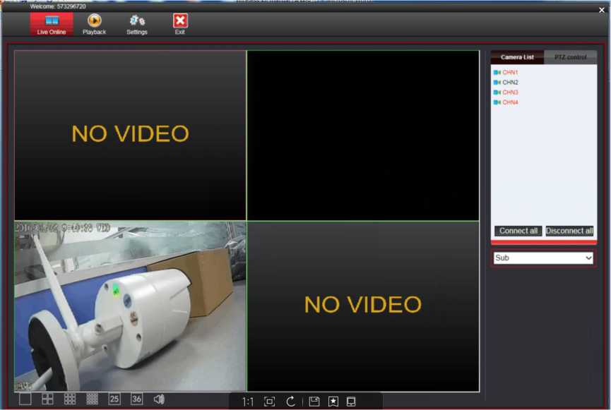
Esee ID login Picture 40
- To search the device ID. Click<System setup>-<Network setup>.
- Please make sure the device is in online status before you login.
User name login 1.Select user name login. Click New account to register a account. After that. Input your new username and password. Click login.
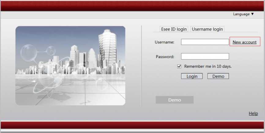
User name login Picture 41
- .Click<Add device>.Input device ID. Input any device set name. and input the device user name and the device password. Click <Add>.The added device is shown in the device list as below:
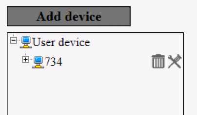
WAN add device Picture 42
- .Click <Live online> on the top left side. Click<Open all> on the top right side. Wait for a min. The image will be shown as below:
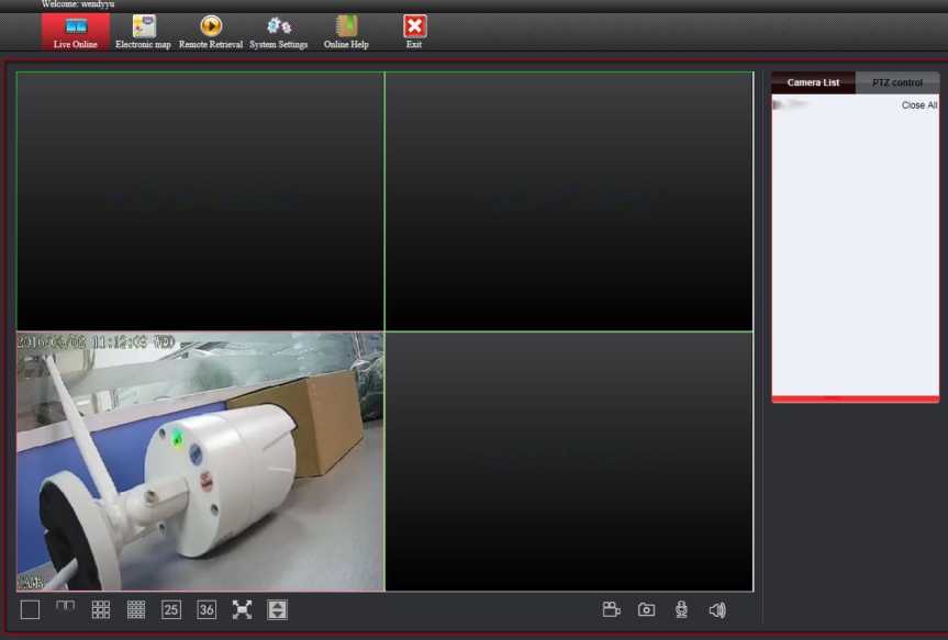
®Ä734
NO VIDEO
NO VIDEO
NO VIDEO
□□
WAN view Picture 43
- To search the device ID. Click<System setup>-<Network setup>.
- Please make sure the device is in online status before you login.
It support Android and Apple system. To install the Eseecloud app. Scan the following QR code.


There are two way to install the Eseecloud app.
- scan the QR code.
- input “eseecloud” in apple store to download it.

There are two ways to install the Eseecloud app.
1.Scan the QR code.
2.Input “www.e-seenet.com/help/download.php “in mobile browser to enter the download page. Click download.
-
- Login
- .Click <Register> to register a new account. Then will pop up a page as
below. Click<+>-<Add device by ID>. As follows:
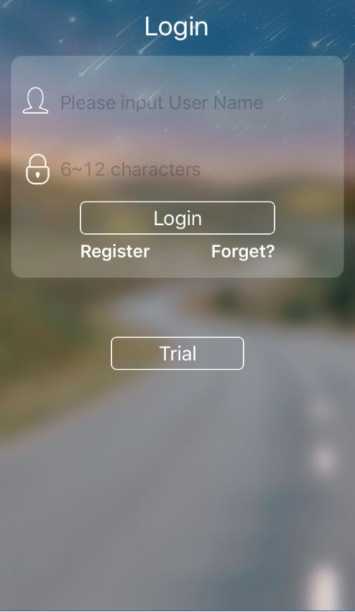

Mobile login Picture 44.45
User also can click<Trial> to add the device.
After login a new account. The device information will be stored on the device server. When you login the account in other mobile phones. The device will automatically display without re-add. If you choose <Trial>. the device information won’t be displayed in other mobile phone.
2.Input device ID or scan the device QR code.(Right click on the NVR.
Click<System setup>-<Network setup>.You can find the device ID or QRcode).Input device user name and password. The default user name is admin. The password is blank.
3.Click the added device. You can view the images on your mobile phone.


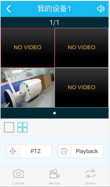
Cloud ID
Descriptions My Devicel
User Name admin
Password
QWERTYU I OP
ASDFGHJKL
♦ ZXCVBNM<3
Mobile add and view Picture 46.47
6.2 Remote playback
In preview page. Click<Playback> to enter playback page. As below:
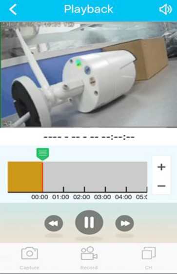
Mobile remote playback Picture 48
- Remote playback can pull a vertical bar to select a specific period of time
- Support 1 channel playback
- When recording a voice. you can also playback with sound
- Click<Record>.can record and playback at the same time. video saved in the phone
- Click the Capture. you can screenshot the current playback screen
- Capture/Record/Stream
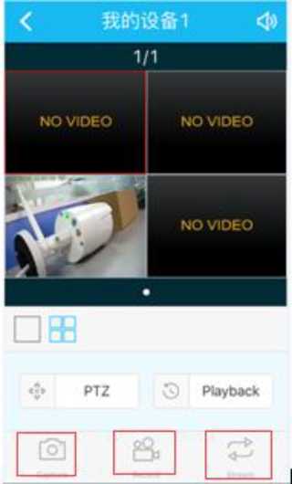
Capture/record/stream Picture 49
Capture :Click it to screenshot the current screen
Record: Click it to record. and the recorded video files are saved in the phone.
Stream: Click it to switch HD or SD mode. HD is the main stream. SD is the sub-stream.
-
- Mobile App Alarm
Mobile app alarm only suitable for the new system. Please upgrade your system before setup mobile app alarm.
Steps: Click<Me> on the bottom right. Click<Alarm settings>. Enable alarm settings. As below. User can click<Notifications> to view alarm information.
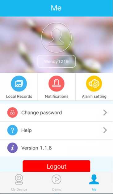
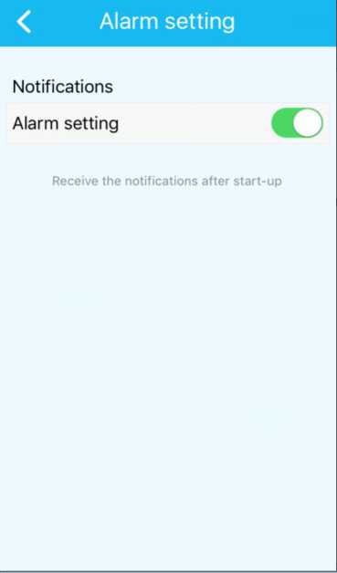
Mobile app alarm Picture 50.51
Note:
1.To setup mobile app alarm. User need to register a account to login .
Otherwise can not set the mobile alarm.
2.Before setup mobile alarm on mobile phone. Please setup on the NVR.
Click<System setup>-<Record setup>-<Video detection>.Select <Mobile app alarm>.
